Back in May 2019 we posted about Steve Olney's HawkRAO amateur radio astronomy station which was the only station in the world to capture the 2019 Vela Pulsar "glitch" which he did so using his RTL-SDR as the radio. The astronomy focused podcast "Astrophiz" recently interviewed Steve in episode 95 where he talks about his amateur radio background, his home made radio telescope, his RTL-SDR and software processing setup, and the Vela glitch.
A pulsar is a rotating neutron star that emits a beam of electromagnetic radiation. If this beam points towards the earth, it can then be observed with a large dish or directional antenna and a radio, like the RTL-SDR. The Vela pulsar is the strongest one in our sky, making it one of the easiest for amateur radio astronomers to receive.
Pulsars are known to have very accurate rotational periods which can be measured by the radio pulse period. However, every now and then some pulsars can "glitch", resulting in the rotational period suddenly increasing. Glitches can't be predicted, but Vela is one of the most commonly observed glitching pulsars.
The HawkRAO amateur radio telescope run by Steve Olney is based in NSW, Australia and consists of a 2 x 2 array of 42-element cross Yagi antennas. The antennas feed into three LNAs and then an RTL-SDR radio receiver.
Astrophiz 95: Steve Olney: From Ham Radio to Radio Astronomy - "The 2019 Vela Glitch"
Feature Interview: This amazing interview features Steve Olney who has established the Hawkesbury Radio Astronomy Observatory in his backyard. Steve has constructed a Yagi antenna array, coupled it with a receiver and observed a pulsar 900 LY away and generated data that has enabled him to be the only person on the planet to observe Vela’s 2019 glitch in radio waves as it happened.
If you're interested in learning more about Vela, Astrophiz podcast episode 93 discusses more about the Vela glitch and why it's important from a scientific point of view.
SpaceAustralia.com have recently been hosting a community science project that involves encouraging teams to build backyard radio telescopes that can detect the arms of our Milky Way Galaxy by receiving the Hydrogen line frequency of 1420 MHz.
This can be achieved at home by building a horn antenna out of cardboard and aluminum foil, and a feed from a tin can. Then the Hydrogen line and galactic plane can be detected by using an RTL-SDR, LNA, and software capable of averaging an FFT spectrum over a long period of time.
While most horn antennas are typically made from four walls, one participant, Vanessa Chapman, has shown that even trash can be used to observe the galaxy. Vanessa's horn antenna is made from multiple cereal boxes lined with aluminum foil and an old tin fuel can. The boxes are held together by some string and propped up by some sticks.
With her cereal box horn antenna combined with an RTL-SDR Blog V3, and an RTL-SDR Blog Wideband LNA, Vanessa was able to use software to average the spectrum over time as the galactic plane passed overhead, revealing the Hydrogen line peak and corresponding doppler shift from the galactic plane.
Vanessa's Hydrogen Line Radio Telescope made from Cereal Boxes
If you don't know what the Hydrogen line is, we'll explain it here. Hydrogen atoms randomly emit photons at a wavelength of 21cm (1420.4058 MHz). Normally a single hydrogen atom will only very rarely emit a photon, but space and the galaxy is filled with many hydrogen atoms so the average effect is an observable RF power spike at 1420.4058 MHz. By pointing a radio telescope at the night sky and integrating/averaging the RF power over time, a power spike indicating the hydrogen line can be observed in a frequency spectrum plot. This can be used for some interesting experiments, for example you could measure the size and shape of our galaxy. Thicker areas of the galaxy will have more hydrogen and thus a larger spike, whereas the spike will be significantly smaller when not pointing within the galactic plane. You can also measure the rotational speed of our galaxy by noting the frequency doppler shift.
We've recently been testing methods to help budding amateur radio astronomers get into the hobby cheaply and easily. We have found that a low cost 2.4 GHz 100 cm x 60 cm parabolic WiFi grid antenna, combined with an RTL-SDR and LNA is sufficient to detect the hydrogen line peak and doppler shifts of the galactic plane. This means that you can create backyard hydrogen line radio telescope for less than US$200, with no complicated construction required.
If you don't know what the hydrogen line is, we'll explain it here. Hydrogen atoms randomly emit photons at a wavelength of 21cm (1420.4058 MHz). Normally a single hydrogen atom will only very rarely emit a photon, but the galaxy and even empty space is filled with many hydrogen atoms, so the average effect is an observable RF power spike at ~1420.4058 MHz. By pointing a radio telescope at the night sky and averaging the RF power over time, a power spike indicating the hydrogen line can be observed in a frequency spectrum plot. This can be used for some interesting experiments, for example you could measure the size and shape of our galaxy. Thicker areas of the galaxy will have more hydrogen and thus a larger spike, whereas the spike will be significantly smaller when pointing at empty space. You can also measure the rotational speed of our galaxy by noting the frequency doppler shift.
The 2.4 GHz parabolic WiFi grid dishes can be found for a cheap at US$49.99 on eBay and for around US$75 on Amazon. Outside of the USA they are typically carried by local wireless communications stores or the local eBay/Amazon equivalent. If you're buying one, be sure to get the 2.4 GHz version and NOT the 5 GHz version. If you can find 1.9 GHz parabolic grid dish, then this is also a good choice. Although we haven't tested it, this larger 2.4 GHz grid dish would probably also work and give slightly better results. WiFi grid antennas have been commonly used for GOES and GK-2A geosynchronous weather satellite reception at 2.4 GHz with RTL-SDRs as well and we have a tutorial on that available on our previous post.
These dishes are linearly polarized but that is okay as hydrogen line emissions are randomly polarized. Ideally we would have a dual polarization (NOT circular polarized) feed, but linear appears to be enough and is much simpler. In addition, the 2.4 GHz feed is obviously not designed for 1420 MHz, but just like with GOES at 1.7 GHz the SWR is low enough that it still works.
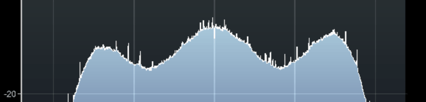
The Gyfcat animation below shows a hydrogen line "drift" scan performed with the 2.4 GHz WiFi dish, an RTL-SDR Blog V3 and a NooElec SAWBird H1 LNA. The scan is performed over one day, and we simply let the rotation of the earth allow the Milky Way to drift over the antenna. The Stellarium software on the left shows the movement of the Milky Way/galactic plane over the course of a day for our location. The dish antenna points straight up into the sky, and we have set Stellarium to look straight up too, so Stellarium sees exactly what our dish antenna is seeing.
You can clearly see that there is a lump in the radio spectrum at around 1420.40 MHz that grows when parts of the Milky Way pass over the antenna. This lump is the hydrogen line being detected. As our Milky Way galaxy is filled with significantly more hydrogen than empty space, we see a larger lump when the antenna points at the Milky Way, and only a very small lump when it points away.
It's important to ignore the very narrowband spikes in the spectrum. These narrowband spikes are simply radio interference from electronics from neighbors - probably TVs or monitors as we note that most of the interference occurs during the day. There is also a large constant spike which appears to be an artifact of the LNA. The LNA we used has a 1420 MHz filter built in, but LCD TVs and other electronics in today's suburban environment spew noise all across the spectrum, even at 1420 MHz.
You can also note that the hydrogen line peak is moving around in frequency as different parts of the galaxy pass overhead. This indicates the doppler shift of the part of the galaxy being observed. Because the arms of the galaxy and the hydrogen in it is rotating at significant speeds, the frequency is doppler shifted relative to us.
Using the power and doppler shift data of the hydrogen line is how astronomers first determined the properties of our galaxy like shape, size and rotational speed. If we continued to scan the sky over a few months, we could eventually build up a full map of our galaxy, like what CCERA have done as explained in this previous post.
Using a specially made hydrogen line LNA with filtering built in will get you better results compared to a general purpose wideband LNA. It may also be mandatory to use one of these LNAs for those living in areas with strong interfering signals from things like cellular and broadcast FM/TV etc.
If you're on a budget, and don't have many strong interfering signals around you, then you get away with using an unfiltered general purpose wideband LNA like an LNA4ALL or our $19 RTL-SDR Blog wideband LNA.
We can generally get away with an unfiltered LNA if we point the antenna straight up towards the sky, or at a high elevation. This avoids most terrestrial sources of noise from leaking into the antenna. However, the H-Line specific LNAs are usually very high gain, and very low noise figure, so can work better for this type of experiment.
An RTL-SDR Blog V3, or any other RTL-SDR with a built in bias tee (~$21.95). An Airspy is also a good choice with good supporting software, but costs a lot more.
A Type N Male to SMA Male adapter (~$7 on Amazon, cheaper elsewhere). Most WiFi grid antennas have an N-female connector so we need to convert to SMA to connect to the RTL-SDR.
A high quality USB extension cable (~$10), just long enough to get to your PC/laptop. We recommend a high quality USB3.0 spec cable, as these have much lower voltage loss over longer runs. If you're using an active cable, make sure it can handle the voltage drop.
Some sort of tripod ($39.99) to mount your dish, or another way to mount it. You could probably even just lay it on the ground.
A Windows PC or Laptop (for this tutorial). A Raspberry Pi could also work with other software or as a TCP server.
Total cost (not including the PC): US$179.40, and probably less if you already have some parts or find similar items priced cheaper elsewhere.
Hardware Setup
The recommended setup is simple. Antenna pointed straight up -> LNA -> RTL-SDR -> USB Cable -> PC.
Cheap and Easy Radio Astronomy Setup with an RTL-SDR and 2.4 GHz WiFi Grid Dish
Detailed instructions below:
Construct the WiFi dish. This is just a matter of putting in a few screws to join the two panels and feed. Make sure the feed is mounted with the long axis matched with the grid direction. Also ensure the reflector is installed.
Mount the dish outside pointing straight up into the sky. Once you are a little more advanced, you could try other elevations or even motorize it, but start with straight up for now. The rotation of the dish does not really matter as hydrogen line emissions are randomly polarized.
Connect the RF side of the LNA to the antenna cable via the N-SMA adapter.
Connect the RTL-SDR to the RF+DC side of the LNA.
Connect a high quality USB cable from the RTL-SDR to your PC. We don't recommend using anything more than a few meters of coax between the LNA and RTL-SDR in order to optimize the signal levels.
Do not use coax between the antenna and LNA. The LNA should be directly connected to the antenna output.
It may also be wise to waterproof your LNA and RTL-SDR if kept outdoors. This can be as simple as putting it in a plastic bag, or old coke bottle sealed with some putty.
Software Setup
In order to detect the hydrogen line we need to use software capable of integrating/averaging many FFT samples over time. Averaging the samples reduces the SDRs quantization noise, allowing the weak hydrogen line peak to be seen. Because the galaxy is moving fairly slowly in the sky, we can safely average for 5-10 minutes at a time.
For Linux, there are various programs that can be used. PICTOR, and rtl-obs are some good choices, but are a little more complicated to set up. But they have some good features like the ability to properly calibrate the results, and some interesting algorithms that could increase the SNR of the hydrogen line detection.
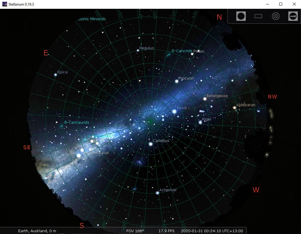
For this tutorial we will keep it as simple as possible, and we will use Windows, with SDR# and a SDR# plugin called "IF Average". We will also use a free astronomy program called Stellarium for tracking the Milky Way's galactic plane across the sky.
Stellarium Setup
Download Stellarium from https://stellarium.org, and download the Windows version using the button up the top.
If you opened Stellarium during the day you won't see any stars due to atmosphere simulation. Hit the 'a' key on the keyboard to disable atmosphere.
Hit the F4 key to go into the options menu. Here we recommend increasing the brightness of the Milky Way to 6.0, to make it really obvious.
We also suggest going to the markings tab, and turning ON the Azimuthal grid, which will provide a marker to Zenith (straight up in the sky).
Check the location shown in the bottom left. If it's not right for you, press F6 to set the correct location.
Use the mouse wheel or pinch controls to zoom out so that the entire sky is visible. Drag the mouse so that the camera is looking at Zenith (straight up into the sky).
As Stellarium will have opened by default in full screen mode, press F11 to go to Windowed mode.
By clicking on an object within the Milky Way or behind it, you can find out the Galactic coordinates of where in the Galaxy you are pointing. This could be useful for comparing with already known results like those shown here. Right click to remove the info text about that object.
Stellarium looking straight up into the sky at the Milky Way
SDRSharp with IF Average Plugin Setup
Install SDRSharp, Blog V3 drivers, and the IF Average Plugin
Download the latest version of SDR# from www.airspy.com. Set up SDR# and the RTL-SDR as described in the Quickstart Guide at www.rtl-sdr.com/QSG.
Rename the original rtlsdr.dll file in the SDR# folder to rtlsdr_old.dll.
Copy over all the .dll files in the Release.zip file.
Rename librtlsdr.dll to rtlsdr.dll.
Download the IF average plugin. Unfortunately the author of the plugin has not maintained his website, and the page is now offline. But the plugin is still available on his Dropbox. Go to Download->Direct Download to download it to your PC. We have also decided to mirror the plugin here on the blog server just in case the Dropbox file goes offline.
Extract the plugin files from the zip file into the SDR# folder.
Open the "Magic sentance.txt" file and copy the <add key...> line.
Open plugins.xml with notepad, and copy and paste in the <add key...> line.
Receiving and Averaging the Hydrogen Line FFT
Open SDR#, select the RTL-SDR, press the start button.
Adjust the RF Gain slider to the maximum, and check the "Offset Tuning" checkbox to enable the bias tee via the V3 driver hack.
Tune to 1420 MHz and use the center tuning button to center the frequency (the button next to the frequency input in SDR#).
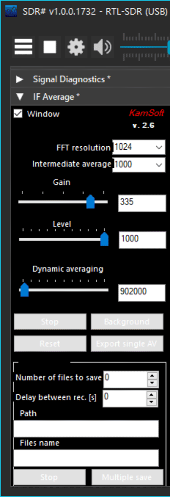
Now on the left scroll down until you find the IF Average plugin that you installed earlier.
We used the following settings which results in a 6-7 minute averaging time (but shorter averaging times would probably also work - try reducing the dynamic averaging a little):
FFT resolution: 1024
Intermediate Average: 1000
Gain: ~335
Level: 1000
Dynamic Averaging: 902000
Calibration: Connect your LNA to the 50 Ohm terminator for initial calibration. If you don't have a 50 Ohm terminator, just leave the antenna disconnected.
Check the "Window" checkbox, and immediately press the "Background" button in order to generate a reference background scan. This scan will be subtracted from subsequent scans thus removing the unwanted curved shape of the RTL-SDR and LNA filters. The first scan will take 6-7 minutes.
Once the background scan is completed, you'll see the words "Corrected background!" in yellow in the top left of the FFT average window.
You can now reconnect the antenna.
Tip: If the FFT Average Window keeps disappearing behind the main SDR# window, push the main SDR# window to the right and bring the IF Average Window to the left so that it does not sit on top of SDR#.
You may need to adjust the Gain and Level sliders a little bit in order to get the FFT graph on the screen. Try to keep the Gain large, as this increases the FFT gain allowing you to see small peaks more clearly.
IF Average SDR# Plugin
At this stage you now just need to wait for the Milky Way to enter your antennas beamwidth, and watch for the H-line peak. The software will continually average the spectrum.
If you want to create a timelapse like the gif shown at the top of the post we can recommend a program called "Chronolapse", which takes a screenshot every X minutes. You can then convert those images into a movie or gif. The IF average plugin can also output data files which could be used for further analysis.
If you do not do the calibration at all, your spectrum will appear quite wavy. Be sure to not confuse those waves with the hydrogen line peak.
If you neglect background calibration, the spectrum will be wavy and not flat.
Example Results
Hydrogen Line Peak (Ignore the Narrowband Peak) Pointing at (-110°, 0°) Galactic CoordinatesHydrogen Line Peak (Ignore the Narrowband Peak) Pointing at (-0°, 0°) Galactic CoordinatesUsing a general purpose wideband LNA still works, but results in a much lower SNR peak.
Other Notes
It is possible to get slightly higher SNR by covering the grid dish with foil, or a metal mesh. However, the improvement appears to be very small, almost negligible since the WiFi feed is only linearly polarized.
Longer integration/average times will spread the peak out more. Smaller integration times may result in less SNR.
You may wish to experiment with an elevation that maximizes the time spent pointing at the Milky Way for your location. Use Stellarium and the time shift feature (F5, or CTRL+ClickDrag) to find the optimal elevation. But lower elevations are more susceptible to man made interference.
A motorized antenna mount would allow you to scan more of the Milky Way in one day. An example build from this previous post here.
Over on YouTube William IU2EFA has been uploading multiple short "meteor scatter" videos. This involves using an RTL-SDR to briefly receive distant radio stations via the RF signal reflecting off the ionized trail left by meteors entering the atmosphere. However, in a similar fashion satellites orbiting the earth can also reflect distant radio stations.
In one of his latest videos William caught a train of Starlink satellites reflecting the signal from the Graves radar in France. To do this he uses a 10 element VHF Yagi, and an RTL-SDR running with HDSDR and SpectrumLab. In the video you can see and hear the change in frequency caused by the doppler shift.
Starlink is a SpaceX project aiming to bring ubiquitous satellite internet to the entire world. Currently 358 Starlink satellites are in orbit, and the end goal is to have 12000.
Thank you to Apostolos for submitting information about his new open source program called "CygnusRFI". CygnusRFI is a tool designed for analyzing radio frequency interference (RFI) with a focus on how it affects satellite ground stations and radio telescopes. We note that in the past we've posted several times about Apostolos' other project called PICTOR, which is an open source radio telescope platform that makes use of RTL-SDR dongles.
Apostolos explains CygnusRFI in the following:
CygnusRFI is an easy-to-use open-source Radio Frequency Interference (RFI) analysis tool, based on Python and GNU Radio Companion (GRC) that is conveniently applicable to any ground station/radio telescope working with a GRC-supported software-defined radio (SDR). In addition to data acquisition, CygnusRFI also carries out automated analysis of the recorded data, producing a series of averaged spectra covering a wide range of frequencies of interest. CygnusRFI is built for ground station operators, radio astronomers, amateur radio operators and anyone who wishes to get an idea of how "radio-quiet" their environment is, using inexpensive instruments like SDRs.
Earlier in the year we posted a tutorial showing how to detect the Galactic Hydrogen Line at home with less than $200 in components. All that is really needed is a 2.4 GHz WiFi dish, an RTL-SDR and an LNA. With this setup it's possible to do home science like determining the size, shape and rotational speed of our own galaxy.
Over on YouTube user Nicks Tech Hobby has successfully replicated our tutorial with similar hardware, and has uploaded a time lapse video showing his results. His success confirms that this is a good way to get introduced into radio astronomy. What's also interesting is that it is possible to spot the Hydrogen line energy on the live waterfall even without averaging/integration.
My first successful attempt to detect galactic hydrogen (Hydrogen line)
Thank you to Geoff for submitting his experience with creating a hydrogen line radio telescope out of an easy to build helical antenna, Raspberry Pi, LNA and an RTL-SDR. The Hydrogen Line is an observable increase in RF power at 1420.4058 MHz created by Hydrogen atoms. It is most easily detected by pointing a directional antenna towards the Milky Way as there are many more hydrogen atoms in our own galaxy. This effect can be used to measure the shape and other properties of our own galaxy.
Earlier in the year we uploaded a tutorial showing how to observe the Hydrogen line with a 2.4 GHz WiFi antenna. In Geoff's setup he used a home made Helical antenna instead. This antenna is basically a long tube with a spiral wire element wrapped around the tube. He also shows how he needed to impedance match the antenna with a triangular piece of copper tape. The result is a directional antenna with about 13 dBi gain. To complete his setup he used a NooElec SAWBird H1+ LNA/Filter, an RTL-SDR Blog V3 dongle and a Raspberry Pi.
The results show a clear increase in RF power at the Hydrogen line frequency when the antenna points at the Milky Way, indicating that the setup works as expected. It's good to see a Helical working for this, as it is fairly light weight and could easily be mounted on a motorized mount to scan the entire sky.
A Hydrogen Line Radio Telescope made with a Helical Antenna.
Just on the back of yesterday's post about a helical antenna Hydrogen line radio telescope, we have another submission. This telescope is a bit more advanced as it consists of a large motorized horn antenna, with a custom made LNA and filter board connected to an RTL-SDR with GNU Radio DSP processing.
Over on Instructables "diyguypt" has posted a full overview of his creation. The horn antenna is first created out of aluminum sheets, and then the waveguide is cut out of copper wire and installed into the can part of the horn. He then notes that he created two custom LNA+filter boards with the Minicircuits PMA2-43LN+ LNA and the Minicircuits BFCN-1445+ filter. This then connects to the RTL-SDR that is accessed via GNU Radio which creates a visualization spectrograph.
He then shows how he made the rotation system out of a salvaged drill motor and two relays, and how he made the Z-Axis control with a stepper motor. The motors are controlled with an Arduino and a gyroscope module.
"diyguypt"'s Hydrogen Line Horn Antenna connected to an RTL-SDR
Over on Facebook Job Geheniau has recently been sharing how he's taken an image of our galaxy (the Milky Way) with a radio telescope consisting of a 1.5 meter dish, RTL-SDR and a few filters and LNAs. In the past we've posted several times about others observing the Hydrogen line with an RTL-SDR, and we have a tutorial here showing how to observe it on a budget.
In this case, Job went a step further than just a single measurement. He used a used a motorized dish and RTL-SDR to scan the entire Milky Way over one month, resulting in a full radio image of the galaxy. As his posts and pdf document are on Facebook and not visible to those without Facebook accounts, we asked for permission to reproduce some of them here for all to see. We have also mirrored his PDF file here, which contains more information about his radio telescope, results and setup.
To make a very long story short. After a month of angel patience (and that says something to me) I managed to take a 'picture' of our entire galaxy (galaxy) in neutral hydrogen! I attach some pictures. If you are more interested, please come after this and PDF with explanation. It was a hell of a job I can tell you. But here's the ' picture s' of the house (230 million light years wide) in which we live and in which we all have a big mouth......
OH YES.. if I'm not mistaken, 1 block of my sightings is 5 million light years (light licht= 300.000 km per second) so maybe we should all take a step back and appreciate our void spot on That atom called Earth. But don't let me mix politics with Science.
Hydrogen Line Image of the Milky Way produced by Job Geheniau
For the Scientists among us... a beautiful plot of the Milky Way Graphically explained in neutral hydrogen....... In short, summarized... if you look up on a beautiful summer evening you will see a beautiful galaxy, this is graphically the same but then on a different frequency than the eye can perceive. own dates of course.....
A composite of Hydrogen Line readings at different points of the Milky Way produced by Job Geheniau
His setup consists of a 1.5m dish, extended to 1.9m with some mesh. A 1420 MHz tuned feed, Mini Circuits ZX6-P33ULN LNA, Bandpass Filter, NooElec SAWBird LNA, Bias-T, RTL-SDR V3, PST Rotator Dish Software, VIRGO software, SDR#, Cartes due Ciel sky chart and a home made netfilter.
He uses a modified version of the VIRGO software to read sky coordinates from a text file, and this points the telescope at each predefined coordinate. He then uses SDR# to record data for 180 seconds before moving on to the next coordinate. The data is then plotted in Excel, and the highest peak is taken at each coordinate and put back into an 8x21 matrix in excel. Conditional formatting is then used to generate a color gradient resulting in a rough map. Then a Gaussian blur is applied, and it is projected over the Galaxy, resulting in the images above.
The Hydrogen Line is an observable increase in RF power at 1420.4058 MHz created by Hydrogen atoms. It is most easily detected by pointing a directional antenna towards the Milky Way as there are many more hydrogen atoms in our own galaxy. This effect can be used to measure the shape and other properties of our own galaxy.
The Amateur Radio Experimenters Group (AREG) recently held an online talk with guest speakers Phil Lock and Bill Cowley, talking about amateur radio astronomy. In the talk they note how they use an RTL-SDR as their radio.
Cheaper electronics has created great possibilities for Amateur Radio Astronomy. This talk will describe a local project to receive and map the distribution of 1420 MHz signals from neutral hydrogen in our galaxy. We briefly describe the history of 21cm RA and why it’s still of great interest to astronomers. We outline some challenges over the last few years in assembling a 2m dish with custom feed, electronics and signal processing, then show recent results from our project.
The image in the thumbnail shows recent signals (May 17th) recorded over a 24 hour period for dish elevation of 53 degrees. The signal changes as the antenna points to different parts of the Milky Way.
Last month we shared information about Job Geheniau's success with using an RTL-SDR dongle to image our galaxy in neutral Hydrogen. Our galaxy is full of neutral Hydrogen, and lots of neutral Hydrogen together results in a detectable radio peak at 1.42 GHz. This peak is called the Hydrogen line. By scanning the galaxy at the Hydrogen line frequency with a 1.5 meter dish on a motorized mount, an RTL-SDR, and a few filters and LNAs, Job is able to create a radio image of our galaxy.
In Job's previous attempt he created an image by pointing the dish antenna at 168 predefined grids calculated to cover the Milky Way, resulting in 168 points of exposure data. In his latest work Job has created an even higher resolution image by taking 903 points of exposure data. Each exposure took 150s and the total 903 exposures took 8 nights to record. Once all data was collected he uses the same process as before, which is to input all the Hydrogen line data into a standard 2D excel sheet, then use conditional formatting to create a heatmap which reveals the image. He then applies a blur and stretches the image into the Mollweide Cartographic which can represent the entire Universe in one image.
If you're interested in Hydrogen line radio astronomy we have a tutorial that will help you observe the Hydrogen line peak on a budget. The tutorial could be improved upon by motorizing the dish, allowing you to create images like the ones above. You might also be interested in a similar project by Marcus Leech who took 5 months of hydrogen line observations with an RTL-SDR in order to create an even higher resolution image.
From calculations depending on the distribution of visible star mass in our galaxy, a certain galactic rotational velocity vs distance from center curve is expected. However, when scientists actually measure the galactic rotation, another curve is found - a curve which should result in the galaxy flying apart. This mismatch in expected vs measured data has given rise to the theory of "dark matter". The theory essentially states that in order to get the measured curve, the galaxy must have more mass, and that this mass must come from non-luminous matter scattered amongst the galaxy which is difficult or impossible to observe.
In the past we have posted about Job Geheniau's radio astronomy projects a few times on this blog. So far he has used an RTL-SDR and radio telescope dish to generate a full radio image of the galaxy at the Hydrogen Line frequency of 1.42 GHz. This project worked by pointing the telescope at one section of the galaxy, measuring the total Hydrogen line power with the RTL-SDR over a number of minutes, then moving the telescope to the next section.
Job's Radio Telescope + Laptop and RTL-SDR Setup
Using the same hardware and techniques to observe the Hydrogen Line frequency, he was now able to measure the rotational curve of our galaxy. When the telescope points to different arms of the galaxy, the Hydrogen line measurement will be doppler shifted differently. The measured doppler shift can be used to figure out the rotational velocity of that particular arm of the galaxy. By measuring the rotational velocity from the center of the galaxy to the outer edges, a curve is created. Job's measured curve matches that seen by professional radio astronomers, confirming the mismatch in expected vs measured data.
A pulsar is a rotating neutron star that emits a beam of electromagnetic radiation. If this beam points towards the earth, it can then be observed with a large dish or directional antenna and a software defined radio. In the past we've posted a few times about Pulsars, and how the HawkRAO amateur radio telescope run by Steve Olney in Australia has observed Pulsar "Glitches" with his RTL-SDR based radio telescope.
Over in Canada, Marcus Leech has also set up a Pulsar radio telescope at the Canadian Centre for Experimental Radio Astronomy (CCERA). Marcus has been featured several times on this blog for his various amateur radio experiments involving SDRs like the RTL-SDR. In one of his latest memos Marcus documents his Pulsar observing capabilities at CCERA (pdf). His memo describes what Pulsars are and how observations are performed, explaining important concepts for observation like de-dispersion and epoch folding.
The rest of the memo shows the antenna dish and feed, the SDR hardware which is a USRP B210 SDR, the reference clock which is a laboratory 0.01PPB rubidium atomic clock and the GNU Radio software created called "stupid_simple_pulsar". The software DSP process is then explained in greater detail. If you're thinking about getting involved in more advanced amateur radio astronomy this document is a good starting point.
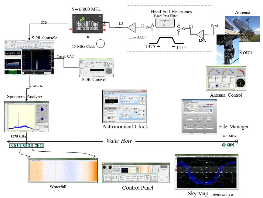
The Search for Extraterrestrial Intelligence (SETI) is an ongoing project that aims to detect radio signals originating from intelligent species somewhere in the universe. Recently Alberto Caballero, a SETI researcher has been proposing a distributed search (project pdf document) with amateur and/or professional radio telescopes. The idea is that multiple stations around the world would monitor a single star for a period of time in order to collect data 24/7. To participate the requirements are a dish 2.1 meters or larger, a motorized mount, and a feed, LNA and radio system able to receive 1 - 4.5 GHz.
An example of a SETI station can be found at SETI Net. Here the owner has a 3M dish on a rotor connected to a HackRF. An LNA and band pass filter are also used at the feed end. SDR Console or SDR# is used to monitor a specific frequency, and the audio is sent into a special automatic SETI analysis program as well as spectrum analysis software. If an interesting signal is detected the software notifies the user, then further analysis can be undertaken.
If you have a suitable radio telescope available and want to participate, you can contact the SETI project via their contact form.
We've posted about Job Geheniau's RTL-SDR radio telescope a few times in the past [1] [2] [3], and every time his results improve. This time is no exception as he's created his highest resolution radio image of the Milky Way to date. We have uploaded his PDF file explaining the project here.
Job used the same hardware as his previous measurements, a 1.5 meter dish, with 2x LNA's, a band pass filter and an RTL-SDR. Over 72 days he used the drift scan technique to collect data in 5 degree increments. The result is a map of our Milky Way galaxy at the neutral Hydrogen frequency of 1420.405 MHz.
JRT - Northern sky Hydrogen Line Survey with RTL-SDR
This image is quite comparable to an image shown in a previous post which was created by Marcus Leech from CCERA who used a 1.8m dish and Airspy.
If you're interested in exploring our Galaxy with an RTL-SDR via Hydrogen Line reception, we have a simple tutorial available here. The ideas presented in the tutorial could be adapted to create an image similar to the above, although with lower resolution.
The Arecibo Radio Telescope has collapsed. Once the largest single dish radio telescope in the world at 305m, Arecibo was mostly used for radio astronomy research. However, the dish was made famous in 1974 for deliberating beaming a message into space as part of a search for extraterrestrial intelligence (SETI) experiment. It also played a part in popular culture, being a part of several famous films such as Golden Eye and Contact.
As part of it's goodbye we thought we'd highlight a few old posts where Arecibo was used together with SDRs for some interesting applications.
The project required finding and researching the original spacecraft documentation, and implementing the modulators and demodulators in GNU Radio. Whilst being successful in communicating with the satellite, ultimately the project failed due to the satellite's nitrogen tanks which had long leaked empty. But the fact that they were even able to find and communicate with the spacecraft using Arecibo was a major achievement. If you're interested in that project, Balint's 2015 talk on YouTube is an interesting watch.
Later in 2017 we saw how Arecibo was used for an Ionospheric heating experiment which involved transmitting 600kW of net power into the Ionosphere. This resulted in SDR users around the world being able to receive the signal. Other posts involve u/moslers Reddit post where he toured Arecibo and showed how they used a familiar program, HDSDR, as part of their monitoring suite.
So goodbye to Arecibo. However, we can look forward to the 500 meter Chinese FAST (Five-hundred-meter Aperture Spherical Radio Telescope) giving us new opportunities for single dish radio observations in the future.
In the past we've posted several times about how 1.42 GHz Hydrogen Line amateur radio telescopes used with RTL-SDRs or other SDRs for Hydrogen line observations of the galaxy. Recently Hackaday ran a post highlighting a project from "PhysicsOpenLab" describing an 11.2 GHz radio telescope that uses an Airspy SDR as the receiver.
Celestial bodies emit radio waves all across the radio spectrum and typically observations can be made anywhere between 20 MHz to 20 GHz. Choosing an optimal frequency it is a tradeoff between antenna size, directivity and avoiding man made noise. For these reasons, observations at 10-12 GHz are most suitable for amateur radio telescopes.
The posts by PhysicsOpenLab are split into two. The first post highlights the hardware used which includes a 1.2m prime focus dish, and 11.2 GHz TV LNB, a wideband amplifier, a SAW filter, a bias tee, and the Airspy SDR. The LNB converts the 11.2 GHz signal down to 1.4 GHz which can be received by the Airspy. Once at 1.4 GHz it's possible then to use existing commercial filters and amplifiers designed for Hydrogen line observations.
The second post explains the GNU Radio based software implementation and the mathematical equations required to understand the gathered data. Finally in this post they also graph some results gathered during a solar and lunar transit.
Finally they note that even a 1.2m dish is quite small for a radio telescopic, but it may be possible to detect the emissions from the Milky Way and other celestial radio sources such as nebulae like Cassiopeia A, Taurus A and Cygnus A a radio galaxy.
A 11.2 GHz 1.2m Amateur Radio Telescope with GNU Radio and Airspy
The hardware used is two RTL-SDR Blog V3 dongles with synchronized oscillators via the selectable clock headers, two 1420 MHz filtered LNAs, a splitter and noise source consisting of a 50 Ohm load and wideband LNA, and a NVIDIA Jetson Nano GPU single board computer. We note that Evans code should also run on our KerberosSDR with some modifications to enable the built in noise source during calibration.
To add to this Evan wrote to us explaining how this code might be used:
Did you see the “picture” of the supermassive black hole shadow released by the Event Horizon Telescope collaboration in 2019? The “ring of fire” or “donut” image? Daniel’s image and that image were created by “aperture synthesis.”
In aperture synthesis, the signals from each pair of antennas distributed across an area can be cross-correlated to measure one component of the 2D Fourier transform of the radio brightness distribution on the sky. But, you need coherent receivers (or REALLY good time stamps) to cross-correlate the signals from the antennas. Get enough pairs of antennas, and you can start to more fully sample the 2D Fourier space of the sky brightness distribution, which you can then use to reconstruct a real image.
This is how distributed radio arrays like the EHT work, as well as localized ones like ALMA or LOFAR.
I should mention that the reason people do this at all is that the image resolution of this technique scales with the distance between the antennas. It no longer depends on the size of the individual dishes. That’s why the EHT used a lot of telescopes very far apart, to see a very compact object very far away.
The Interferometer Setup with Noise Calibration Hardware Attached
The 2021 Software Defined Radio Academy conference was held online this year on June 26/27 and the talks have been recently uploaded to YouTube. There are some interesting talks this year including a presentation on various SDR related topics including Electrosense, gr-rpitx, 21cm radio astronomy with low cost SDR hardware, and using deep learning neural networks for automatic signal identification. Our favorite talks and blurbs are collected below for easy access, and the full set of talks can be found on their YouTube channel.
Dr. Henning Paul: Building a flexible Multi-Antenna-capable SDR using open Source
The availability of Open Source software components enables the ambitious hardware hacker to design their own powerful SDR. This talk is the follow-up to the talk on Scientific SDR and recapitulates the steps towards the current design of a Homebrew SDR based on a Xilinx Zynq SoC using the Linux kernel and other Open Source components. Furthermore, one of its applications, receiving shortwave radio with antenna diversity is presented.
Jean-Michel Friedt: GNURadio compatible gen. purpose SDR emitter using RasPi4 PLL
GNU Radio, the Raspberry Pi single board computer and Digital Video Broadcast Terrestrial receivers make an awesome combination for educational purposes of Software Defined Radio. gr-rpitx aims at complementing these tools with emitting capabilities, combined with the flexibility of GNU Radio.
Sreeraj Radjendran: Knowledge extraction from wireless spectrum data
In this half-hour talk, the need for large scale wireless spectrum monitoring will be discussed. A short introduction to a large scale wireless spectrum monitoring framework, Electrosense, will be given. Furthermore, how anomaly detection and signal classification can be performed using the collected data will also be discussed. Insights to the major problems with state-of-the-art machine learning models will also be discussed in this context.
Stefan Scholl, DC9ST: Classification of shortwave radio signals with deep learning
Automatic mode classification of radio signals in the HF band is a valueable tool for band monitoring, operation of rare transmission modes and future applications of cognitive radio. In recent years, machine learning has established as a general and very powerful approach to classification problems. The presentation first provides an introduction to neural networks and deep learning. Then neural nets are applied to the task of radio signal classification. The result is an experimental deep convolutional neural net (CNN), that can distinguish between 18 different transmission modes occurring in the HF band, such as AM, SSB, Morse, RTTY, Olivia, etc.
Marcus Leech: Mapping the sky at 21cm: Gnuradio and Radio Astronomy
We show the results of a year-long sky survey at the 21cm hydrogen line, producing an intensity map of the sky covering a declination range from -35 to +75DEG. We discuss the software tools used, Gnu Radio signal flows, and the hardware aspects of the instrument.
Over on Facebook Job Geheniau has posted results from his latest radio astronomy experiment which involves imaging the Cygnus-X star forming region at 1424 MHz with a 1.9m radio telescope, an RTL-SDR and some additional filtering and LNAs. In the past we've posted about Geheniau's previous work which involved imaging the entire Milky Way at 1420 MHz, and measuring the basis for the dark matter hypothesis with a similar process and the same equipment. His latest post reads:
Cygnus-X is a massive star-forming region in the constellation Cygnus at a distance of 1.4 kiloparsecs (4600 light-years) from the Sun.
Cygnus-X has a size of 200 parsecs and contains the largest number of massive protostars and the largest stellar association within 2 kiloparsecs of the Sun. Cyg X is also associated with one of the largest molecular clouds known, with a mass of 3 million solar masses. [Wikipedia]
The idea: To take a radio picture of the Cygnus complex (Cygnus A + Cygnus X) with my 1.9 meter radio telescope. Equipment: 1.5 - 1.9 meter radio telescope Mini Circuits LNA ZX60-ULN33+ Bandpass filter 1200-1700 MHz 2nd LNA RTL-SDR VirgoSoft
Implementation: Multiple 4-hour drift scans of the Cygnus complex and beyond. In order not to be affected by HI at 1420 MHz, measurements were made at 1424 MHz. At this frequency there is Synchrotron radiation and no neutral hydrogen emission. To be sure that no Milky Way synchrotron radiation is measured there would be no or hardly any measurable power change outside the Cygnus complex during the drift scan. This was also observed in these measurements and also confirmed earlier in test measurements.
A total of 7 drift scans of 4 hours were made at 1424 MHz. Because the start of the driftscan generates a lot of wrong data (the 'cooling down/warming up' of the RTL-SDR), this has been removed in the measurements. The measurement starts at 2000 seconds and is always aborted at 12000 seconds in post-processing.
7 shots from RA 19 to RA 22. The declination varied each observation from DEC 36 to 43 degrees.
Because not every driftscan was perfect (heavy clouds gave worse results anyway as well as wind/rain or rfi) a total of 15 measurements were done, of which 7 were thus acceptable enough for editing.
In the end JRT performed measurements from 24 September to 9 October. Patience is a good thing.
Results: By editing the driftscan data in Excel with Conditional Format (giving color to the data) the final result is a 'radio photo' of the complex.
Of course, in view of the dish diameter, the beam is 8 degrees and thus a somewhat rough image of the Cygnus complex is sketched here.
Job Geheniau - Netherlands.
Cygnus-X Imaged at 1424 MHz with an RTL-SDR based home radio telescope.